


There are many people who understand dimensional tolerances but don’t know what Geometric Tolerance is. Geometric tolerancing is the process of quantifying the shape of a circle, square, etc., so that it can be managed in a standardized manner.
◆ How “round” is the roundness?
◆ How straight is straightness?
◆ How “flat” is the flatness?
You may have a rough idea of what these definitions are, right? But do you know what positional degree is? The definition is, are you in a “defined position”? I’m not sure. Positional degree is difficult to define on a drawing, but it is even more difficult to measure and evaluate.
In this article, I would like to focus on positional tolerancing, which I personally had a hard time understanding. As mentioned above, the positional degree is a standardized measure of the degree to which a part stays in a given position. As mentioned above, the position degree is a standardized measure of the degree of “how long you are in a given position.
The definition of positionality is, are you in a “defined position”? Do you know what that is?
I don’t understand at all.
1. What is the position degree of geometric tolerance?
To break it down a little more, position here refers to the evaluation of how much the center position of a shape deviates from a certain standard (line, origin). There are two types of drawings that show the position of the holes in the X and Y axis directions, as shown below.
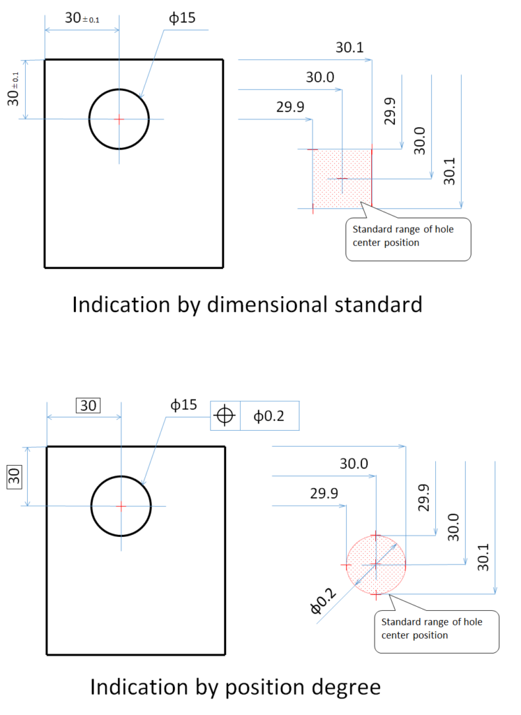
The above drawing is a dimensional drawing and the below drawing is a position degree drawing. They are similar standards, but they are strictly different. In the case of dimensional indication, the standard is whether the center of the φ15 hole is located at 29.9 to 30.1 in the XY axis direction, while in the case of position degree, the standard is whether the center of the φ15 hole is located at 30.1 in the XY axis direction. In contrast, the positional degree specifies whether the center of the φ15 hole is within the range of φ0.2 based on the XY axis of 30.0. In this way, positional degree is defined as “Is the diameter within the standard (φ0.2) range for a certain reference (X30 and Y30)? is defined.
The diameter here is strictly cylindrical, but since it depends on how it is measured, it can be considered a two-dimensional diameter. The measurement is done with a CMM or a projector, but it can also be done with pitch calipers. The distance from the two reference axes to the XY axis is measured, and the position degree is calculated from the distance.
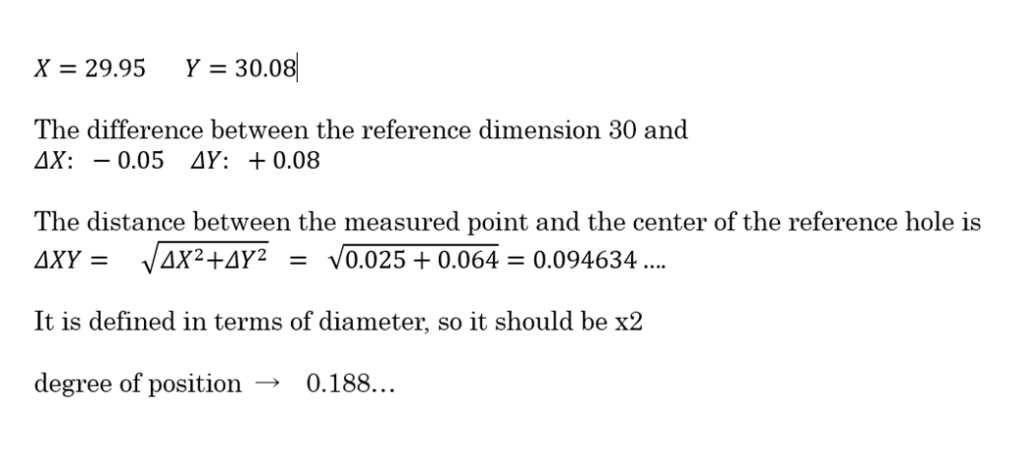
The result shows that the standard for the position degree is 0.2, so if it is 0.188, it is within the standard.
2.Position degree including datum and PCD
One more example.
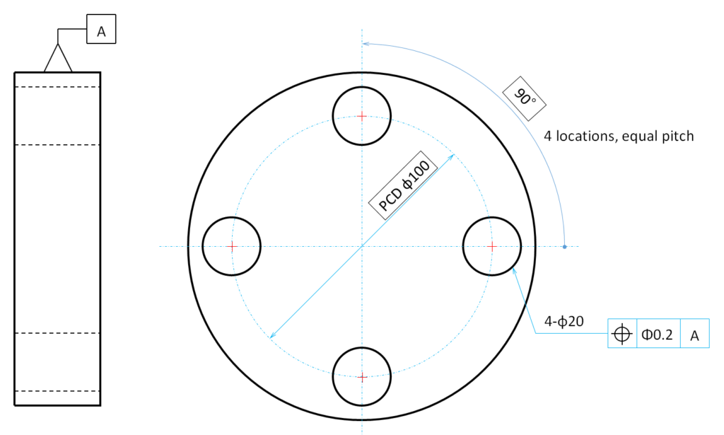
A disk as shown in the figure has four through holes of φ20 at equal intervals on PCDφ100. The standard for the position degree is 0.2, and the standard is [A]. For your reference, PCD stands for Pitch Circle Diameter, which means the pitch dimension on a virtual circle.
First, let’s check the standard.
PCDφ100″ and “90°” are enclosed in □ (squares).
Next, you see that [A] is indicated as the datum plane. This refers to the outer diameter, so the center of the outer diameter is the reference.
In summary, the standard is “PCDφ100,” “90°,” and “center of outer diameter.
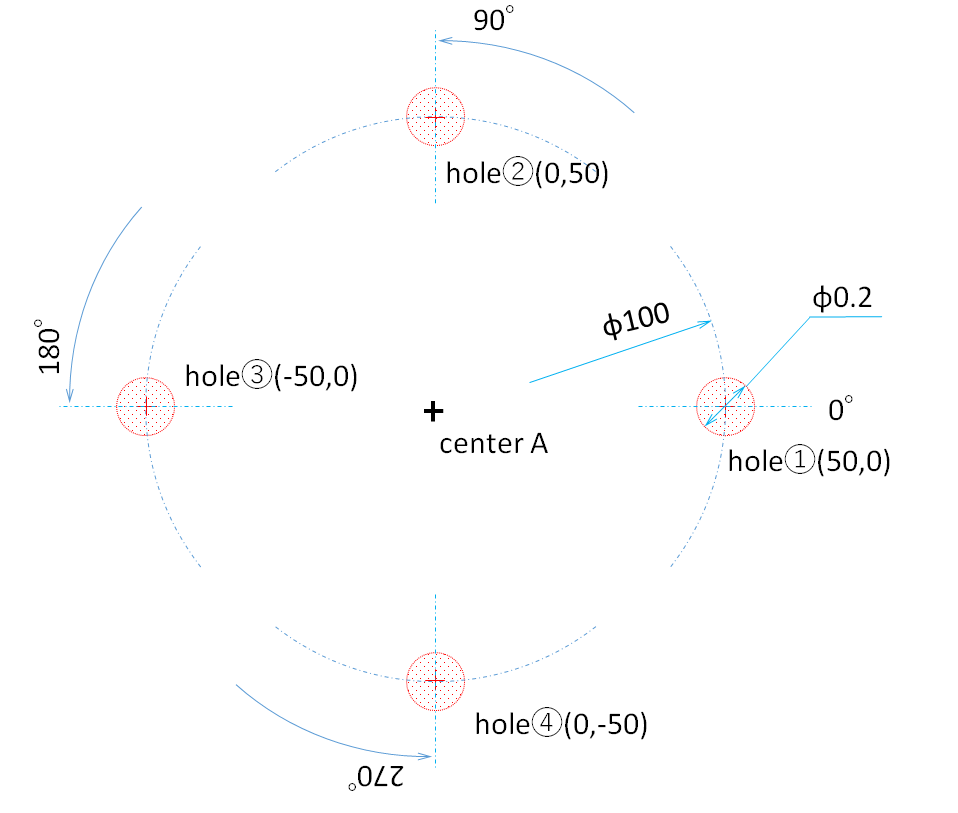
Applying this to each φ20 hole, the reference center position (coordinates) for each hole is as follows
However, this alone may cause problems when measuring. When measuring, the reference center is determined from the outer diameter, but the reference axis cannot be determined from the outer diameter. This is where the reference axis is determined, but in fact, there is no set way to set this axis. The following is based on my personal experience, so please refer to it as an example rather than a correct answer.
3.Reference axis to be set for position degree measurement
In order to determine the reference axis, we need the elements of a line. To draw a line, we need to connect two points, and we can choose two or more from each circle center point. There are two ways to choose a center point: 1) 0° from the reference point and 2) 0° and 180° from the center of the circle.
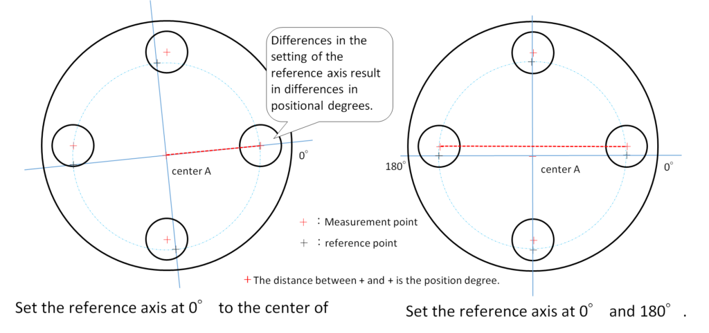
If you choose B, the displacement in the Y direction will be zero for the 0° circle center, but the position of the other holes will be larger. However, if you use A, it is based on 0° and 180°, so it will deviate from the origin in the Y direction, but the position degree of other holes will not increase. The reason for regulating the positional degree in t
In the left figure ➀, the amount of displacement in the Y direction is zero for the center of the circle at 0°, but the positions of the other holes become larger. However, in the figure on the right (2), since 0° and 180° are used as the reference points, there will be a shift in the Y direction from the origin, but the positional degree of the other holes will not increase. As you can see from the figure, even though the measurement is made with the same accuracy, the difference in the way the reference axis is set makes a big difference in the values.
One of the reasons for regulating the position degree in the drawing is to control the mounting accuracy with the mating parts. When actually installing the part, each hole is aligned so that all the holes are in contact with the mating part, so I think that method (2) is suitable for the purpose of measurement. However, method (2) can only be used for even-numbered holes, so if you have odd-numbered holes, you will have to choose method (1). Even if the position degree is NG in ①, it is often the case that it can be installed without difficulty when installed on the actual mating part.
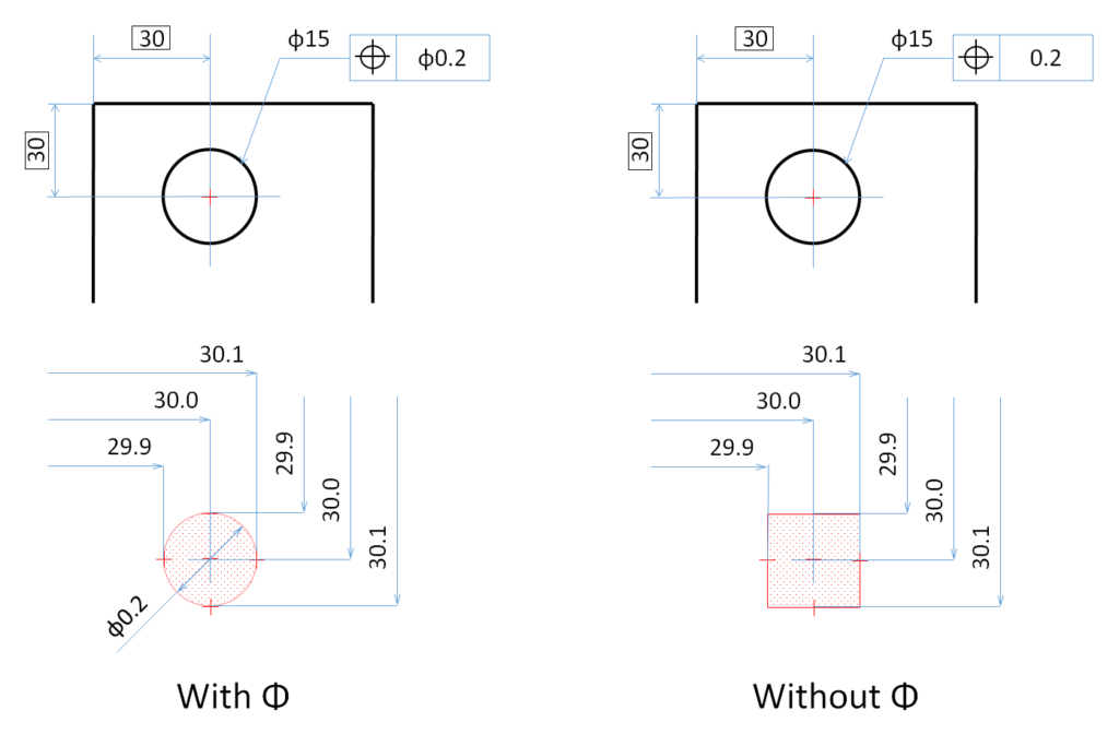
4.Standard range with Φ and without Φ
In the previous sections, we explained that the value of the position degree is “Φ“, and that if the center position is within a circle of diameter “Φ“, it can be judged to have passed. However, there are two types of this value, “with Φ” and “without Φ,” and the range within which it is judged to be acceptable differs. The details are shown in the figure below, which is often overlooked at first glance. In particular, when measuring with a 3D measuring machine, it is possible to select “with Φ” or “without Φ” in the calculation application at the time of measurement, so be careful not to overlook this convention. In particular, when measuring with a 3D measuring machine, “with Φ” and “without Φ” can be selected in the calculation application at the time of measurement.
the end

コメント